User-defined Grids
There are five predefined grid settings (1x1, 2x2, 2x3, 3x4, 4x6) provided for the display monitor. However, it is possible to create custom grids for each project.
New grids can be defined in a XML file. Further adaptions are necessary if the created grids shall also be available in the object explorer.
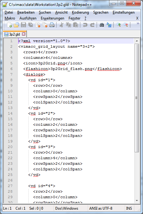
XML file
The following tags and properties must be used to define new grids.
Example:
<?xml version="1.0"?>
<vimacc_grid_layout name="1+2">
<rows>2</rows>
<columns>3</columns>
<dialogs>
<vd id="1">
<row>0</row>
<column>0</column>
<rowSpan>1</rowSpan>
<colSpan>1</colSpan>
</vd>
</dialogs>
</vimacc_grid_layout>
rows, columns
The tags "rows" and "columns" define the size of the entire area.
dialogs>
The dialogs are defined via the "vd" entries. Each dialog needs an explicit number given by the "id" parameter (ongoing and starting at 1). E.g. <vd id="3"> </vd>.
row, column
The properties "row" and "column" defines the position within the entire field. E.g. <row>1</row> <column>2</column> means that this dialog starts in the row with index 1 (which means the second row) and the third column (index 2).
rowSpan, colSpan
In addition the size (how many columns and rows are occupied) of the dialog can be defined. For 1x1 e.g. <rowSpan>1</rowSpan> <colSpan>1</colSpan> must be defined.
Special parameters
Moreover. the following special parameters can be defined for the layout.
- <defaultvd>1</defaultvd> - defines with which dialog all other dialogs will swap places after a double click. This is useful if e.g. a grid with one big and two small dialogs is used. In case that this parameter is not set, the default behavior is used (a dialog is maximized by a double click).
- <icon>1p2Grid.png</icon> - defines the icon which shall be displayed in the toolbar of the vimacc workstation. The icon (png, jpg, svg) must be in the same directory as the layout.
- <flashicon>1p2Grid_flash.png</flashicon> - defines the icon which shall be displayed in case of an alert
Example XML file and activation of grids
The following grid shall be used in the object explorer.

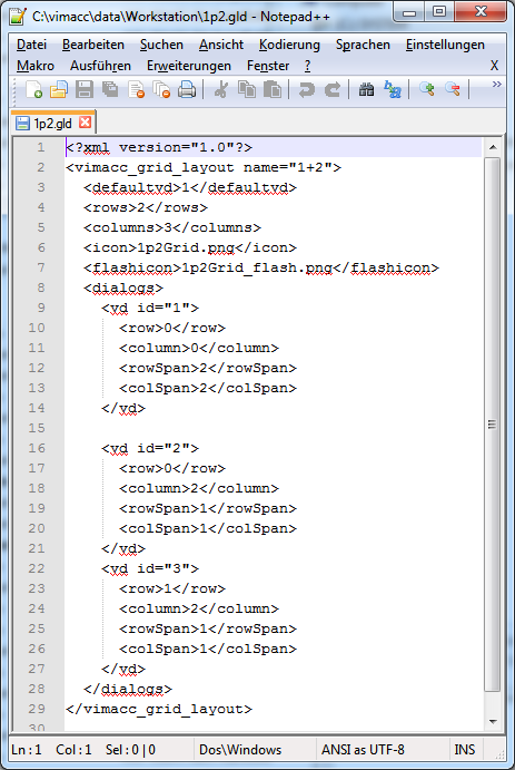
The grid name is defined as "1+2". The corresponding XML file is as follows:
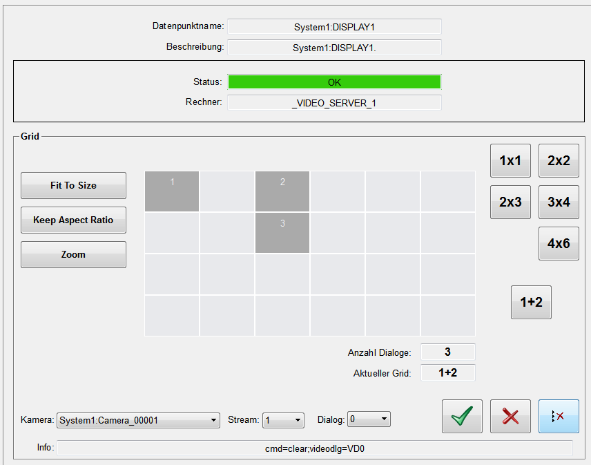
A 4x6 matrix is available in the object explorer for grids for display monitors and configurations. If other grids than the default grids shall be displayed within this matrix, the new grids must be defined in the following functions:
- VIDEO_OA_paraList_getDisplayNamesForGrid()
- VIDEO_OA_paraListGetVisibleDisplaysForGridname()
These functions can be found in the VIDEO_OA_paraListFunctions_custom.ctl library (<wincc_oa_path>\Video_3.13\scripts\libs). The function VIDEO_OA_paraListGetVisibleDisplaysForGridname defines which of the 24 fields shall be used for the display. The function VIDEO_OA_paraList_getDisplayNamesForGrid defines which display number shall be represented by a field.
Furthermore, a new button which calls the new grid must be implemented on the panels/VIDEO_OA/VIDEO_OA_objectExplorer_sub_frontDisplay.pnl panel. One of the existing buttons can be used as template. After that the new grid can be used.
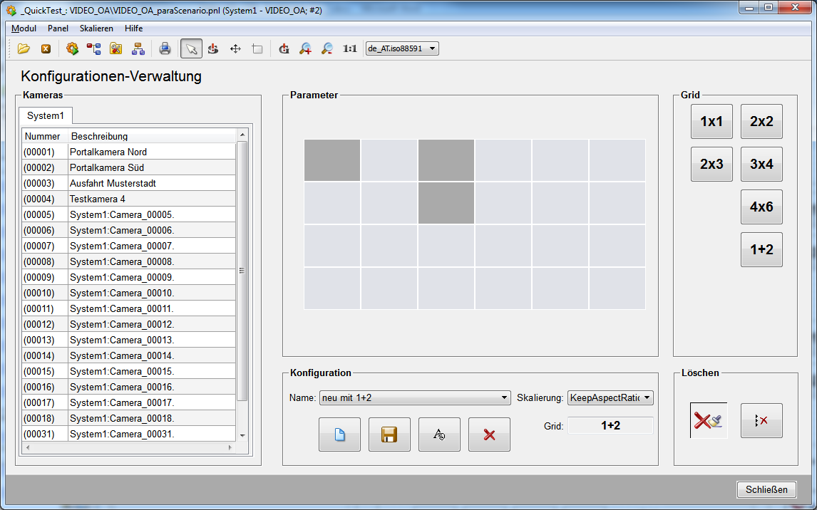
A new button which calls the new grid must also be defined in the panels/VIDEO_OA/VIDEO_OA_paraScenario.pnl panel in order to use the grid here too.
Custom grids can only be used for display monitors and not EWOs. If a configuration with a custom grid is displayed on an EWO, the EWO automatically uses a grid with a appropriate number of dialogs. E.g. the EWO will choose the grid 2x2 instead of the custom grid "2+1".
Further examples
There are further example grids in addition to the "1+2" grid. They can be used (with an appropriate license and XML file) by inserting the corresponding buttons.
"2+1":

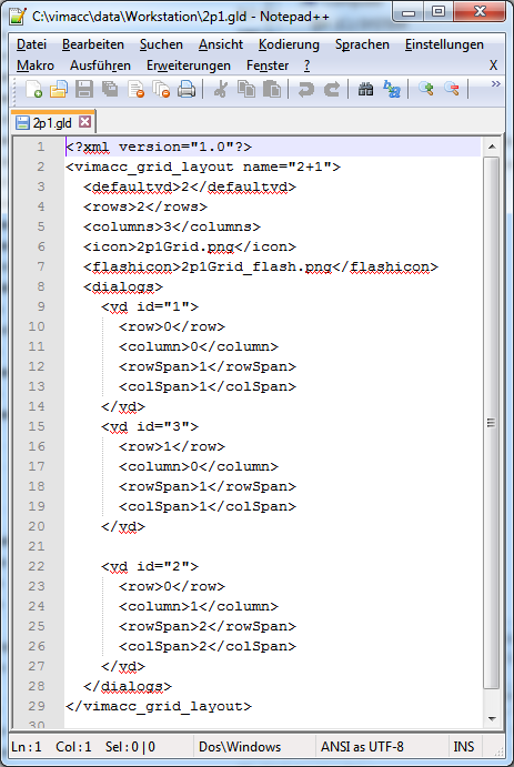
3+2:

