System Overview

The goal of this panel is to provide the user with a general overview of the health of the disaster recovery system. It shows:
- The PSS and SSS error status with alert lines (errors that occur during a synchronization process are displayed) in the middle section of the panel.
- The connection between the systems.
- The connection to the database.
- The active/passive status of the systems.
If the status changes again while the UI manager is still waiting for responses, it is an "unexpected change in the redundancy status".
Redu Manager has a “blocking time” (3 seconds by default) during which the redundancy change is not allowed to take place. The buttons are locked in the user interface. The blocking time can be specified via the activeChangeInterval config entry.
In addition, from this panel you can activate manual switching between systems and start general synchronization of online data and alert status (configuration synchronization).
The alerts for the respective server system are displayed in the tables in the middle of the system overview panel. If the maximum parsing time (maxParseTime) is exceeded by the event manager when building the queries for synchronizing the online values, a warning is displayed in the table. When this error occurs, online values between SSS and PSS cannot be synchronized correctly.
Left-click on the area of a server system (see figure above) of the primary or secondary server system to open the System overview panel in redundant systems. The output of the current and maximum error status is also displayed in this area.
If one of the systems is in split mode, this will be shown in the system overview panel and file synchronization will not be possible during this time.
Split mode can only be enabled on the primary server system. On the secondary server system, this option is disabled.

Colors of different states in the System Overview panel
PSS/SSS


Connection between WinCC OA and historical database (Oracle® RDB or PostgreSQL®):


Visualization of a crash of the active server in the system overview panel
If all 4 servers of the DRS are running, the active servers are displayed with the
color green in the background and the passive servers with the color 
If the active server of the PSS/SSS crashes, its background color changes to red and the background color of the passive server changes to green as it became active.
If the passive server of the PSS/SSS crashes, its background color changes to red and
the background color of the active server remains green. When the passive server is
restarted, its background changes back to  .
.
Buttons
- Backend details
The backend details are only shown for DRS - NGA. The button opens the backend overview:
Figure 9. Backend Overview 
-
Send all Values
Sends all online data and the alert status to the other system. This virtually corresponds to a general synchronization of the systems.
-
Set Active
Sets the corresponding system to active and automatically sets the other to passive. That means that a manual switchover is performed.
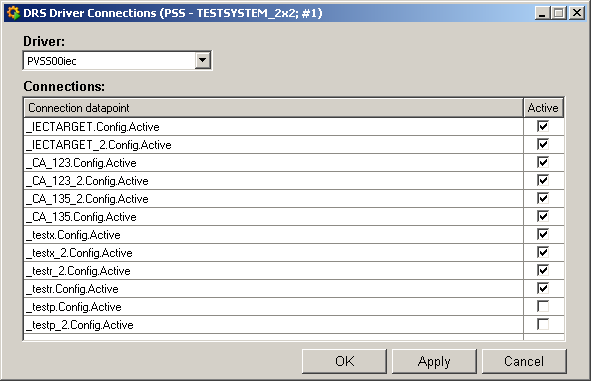
- DRS driver connection
Allows setting a driver connection, which is managed by the DRS (see also Configuration -> Managers) active/inactive from the DRS point of view.

This panel can be used to activate or deactivate the driver connections of all drivers managed by the DRS from the DRS point of view. The actual status assigned to the connections on the PSS and SSS depends on the driver mode used.
- in mode 0 or 2 -> connection becomes active on the PSS and SSS
- in mode 1 -> connection becomes active on the active system and inactive on the passive system
Configuration synchronization
Triggers manual configuration synchronization between PSS and SSS.User/Password
Click this button to open the panel for synchronization of user data between PSS and SSS.
Historical synchronizationOpens the panel that can be used to activate the synchronization of historical data (see Database Synchronization).
CloseCloses the system overview.
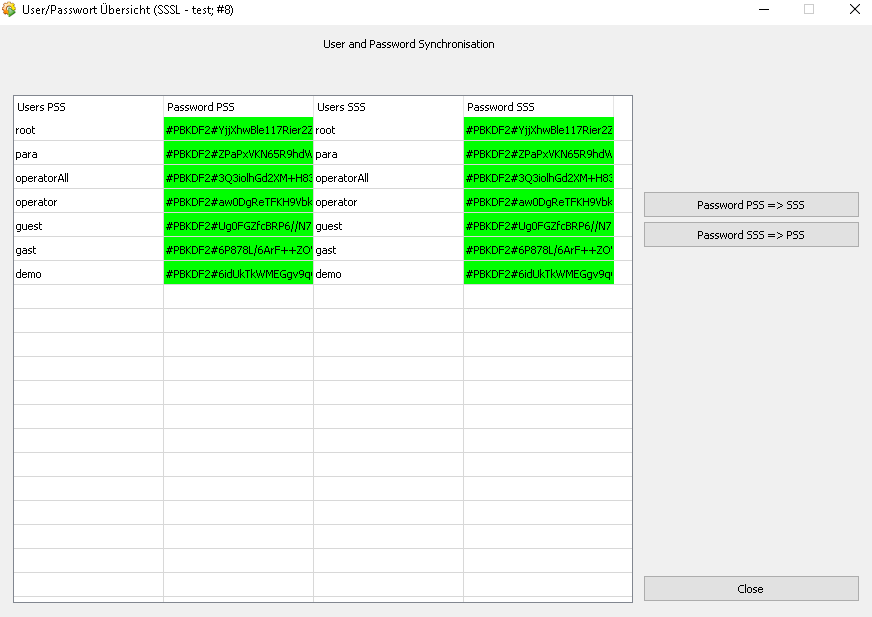
Synchronization of user data and passwords
Click on the User/Password button in order to open the panel for synchronizing user data and passwords between the PSS and the SSS.

In the table, all users of the respective system (PSS and SSS) are automatically listed with their passwords.
The following commands can be sent via the buttons here:
-
Password PSS => SSS
Synchronises the password of the selected user from the PSS to the SSS.
-
Password SSS => PSS
Synchronises the password of the selected user from the SSS to the PSS.
-
Synchronization PSS => SSS
Performs a complete synchronization of the user data from the PSS to the SSS.
-
Refresh
Updates the table.
-
Close
Closes the panel.


