Time Stamp Push Protocol (TSPP)
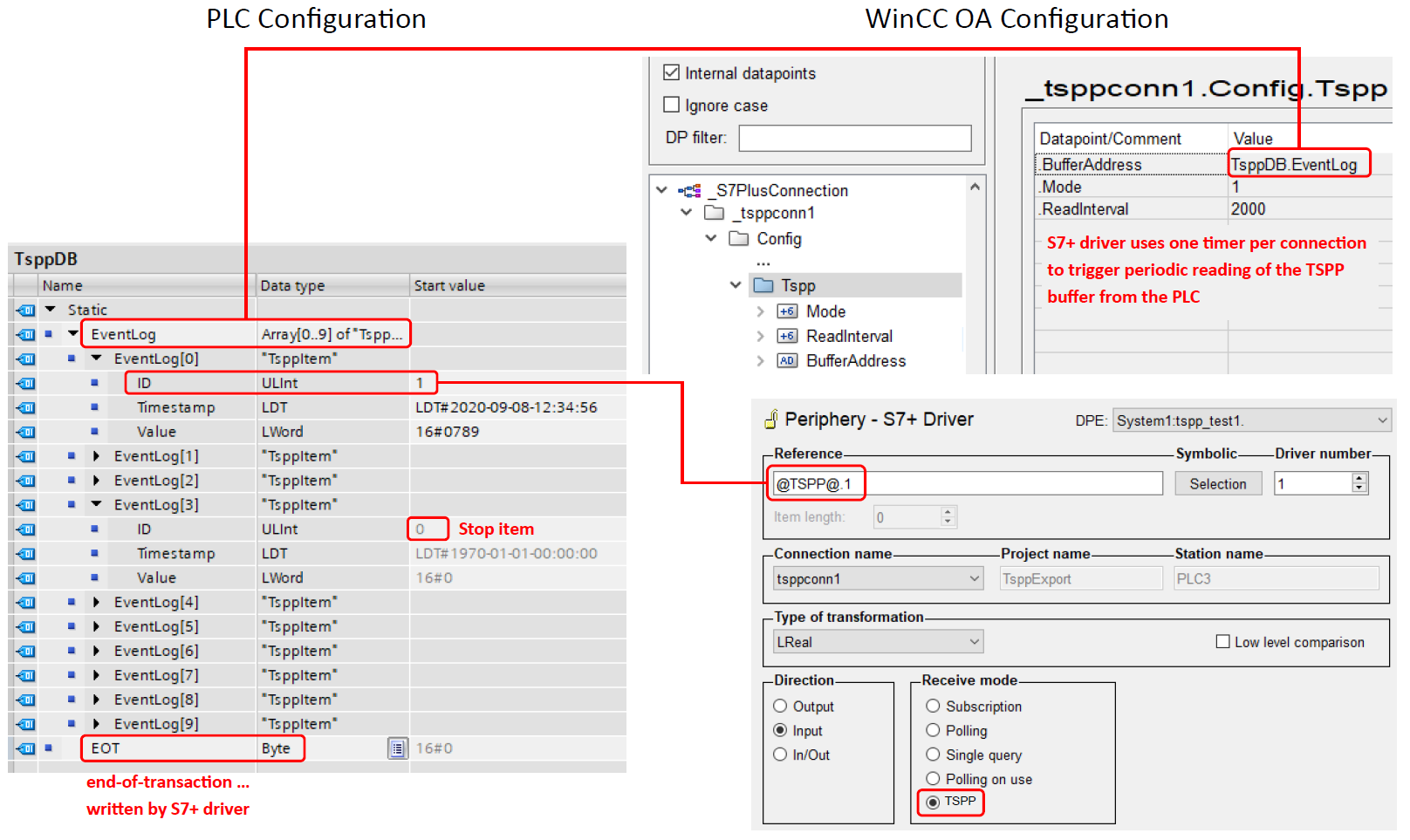
This chapter acts as a guide to the "TSPP" tab. This tab provides configuration options for using TSPP with the S7Plus driver.
TSPP is an abbreviation for the Time Stamp Push Protocol and has been initially implemented for the classic S7 driver. A description of the function and basic protocol information can be found under S7 - TSPP.

General information
Following general notes must be considered when using TSPP:
- TSPP can only be used to read values from the PLC.
- For using TSPP no complex data types (arrays) are supported.
- Configured TSPP addresses use the prefix "@TSPP@."
- The value of the Timestamp element (see description below) is written to the timestamp of the original config for the configured DPE.
TSPP Data Structure
The overall TSPP buffer data structure must contain an array of TSPP items followed by an EOT (End-of-Transaction) byte, see example below.
Example
EventLog[0..n]
  + EventLog[0]
  - EventLog[1]
    ID
    Timestamp
    Value
  + EventLog[2]
  ...
  + EventLog[n]
- EOT- Each entry of the TSPP buffer items must adhere to the defined TSPP Item Structure as described below.
- The end of the buffer array or an ID value of 0 (see TSPP Item structure below) is considered as end the transmission and will stop the reading of the buffer items.
- The value written to EOT contains the active session number on bits 0 and 1 and an indicator for the redundant system on bit 2.
TSPP Item Structure
The TSPP item within the buffer address must contain following structure:
| Element Name | Data Type in TIA Portal |
|---|---|
| ID | UDInt |
| Value | DWord |
| Timestamp | LDT/Date_and_Time |
Example
EventLog
  EventLog[0]
    ID
    Value
    Timestamp
  EventLog[1]
    ID
    Value
    Timestamp
  ...
  EventLog[9]
    ID
    Value
    Timestamp
Redundancy
Following notes must be considered when using TSPP in a redundant project:
- When activating the config entry "[s7plus] onlyActivePolls" in a redundant system only the active driver will poll from the TSPP buffer. This allows to prevent any problems with possibly limited PLC resources.
Configuration Interface
TSPP configuration
Set TSPP Mode active
Allows to enable/disable the TSPP mode.
Read interval
Defines the interval (in Milliseconds) for reading the specified TSPP buffer of the PLC.
Buffer address configuration
Buffer address
Using the "Select" button the buffer address can be selected.
